Definition VLAN | Virtual Local Area Network What is a VLAN?
A VLAN is a logical subnetwork of a physical local area network (LAN). It divides the local network into logical segments and forms its own broadcast domains. Virtual Local Area Networks can be realised port-based or with the help of VLAN tags. VLAN technology is used, for example, to prioritise data traffic or to logically separate data streams.
A VLAN is a logical sub-network of a physical local area network (LAN).
VLAN is the acronym for Virtual Local Area Network. It is a logical sub-network of a physical local area network (LAN). The Virtual Local Area Network forms a logical network segment and its own broadcast domain. VLANs can extend across several switches. They can be port-based or realised with the help of tagging. The IEEE standard 802.1Q forms the technical basis for VLAN tagging. It works on the second layer of the OSI reference model and allows tagging information to be added to Ethernet frames. Tagging allows many logically separated VLANs to be transmitted simultaneously via a single network cable. Typical areas of application for VLANs are the prioritisation of data traffic or the logical separation of data streams.
Realisation options for virtual local area networks
There are various realisation options for Virtual Local Area Networks. In principle, VLANs can be implemented port-based or with the help of tagging.
With port-based VLANs, individual ports of a manageable switch are permanently assigned to a specific VLAN. This creates several logical networks on one switch. Port-based VLANs are configured statically. They can also extend across several switches. In this case, the switches are connected via so-called trunk ports. They transmit the membership information of a specific Ethernet frame in the form of tags, as described in the next section.
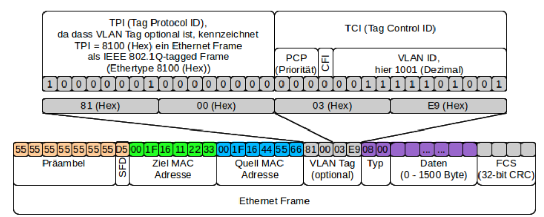
If VLANs are realised via tagging, there is no need to statically assign a switch port to a specific VLAN. Individual Ethernet frames are labelled with tags that define the affiliation to a specific Virtual Local Area Network. These VLANs are therefore also referred to as frame-based. The technical basis for tagging is the IEEE standard 802.1Q. The length of a VLAN tag is 32 bits. It is inserted in the Ethernet frame directly after the sender MAC address. A tag consists of a protocol ID with a length of two bytes. This is followed by a priority field with a length of three bits, one bit for the Canonical Format Identifier (CFI) and twelve bits for the VLAN ID. Due to the length of twelve bits, a total of 4,096 different VLANs can be labelled. Tagging according to IEEE 802.1Q is the more modern form of VLAN implementation and has largely replaced port-based VLANs.
Reasons for the use of Virtual Local Area Networks
The logical segmentation of physical local networks using Virtual Local Area Networks is used for various reasons. Typical reasons are:
- Logical separation of data streams
- Separation of productive environments and test environments
- Limitation of broadcast domains and reduction of broadcast traffic
- Separating network segments for security reasons
- Separation of publicly accessible and internally accessible systems - separation of public and private traffic
- Prioritisation of data streams
- Separation of VoIP and data traffic
- Mapping of departmental structures regardless of the location of the end devices
VLAN types
You can basically implement VLANs in two ways:
- As port-based VLANs (untagged)
- as tagged VLANs
Port-based VLANs
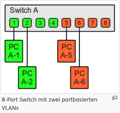
With port-based VLANs, you simply divide a single physical switch into several logical switches. In the following example, we divide a physical 8-port switch (Switch A) into two logical switches:
8-port switch with two port-based VLANs Switch A  Switch port VLAN ID Connected device 1 1
(green)
PC A-1 2 PC A-2 3 (not in use) 4 (not in use) 5 2
(orange)
PC A-5 6 PC A-6 7 (not in use) 8 (not in use)
Although all PCs are connected to a physical switch, only the following PCs can communicate with each other due to the VLAN configuration:
PC A-1 with PC A-2 PC A-5 with PC A-6
Let's assume that there are also four PCs in the neighbouring room. Now PC B-1 and PC B-2 should be able to communicate with PC A-1 and PC A-2 in the first room. It should also be possible for PC B-5 and PC B-6 from room 2 to communicate with PC A-5 and PC A-6 in room 1.
We have another switch in room 2:
Switch B Switch port VLAN ID Connected device 1 1
(green)
PC B-1 2 PC B-2 3 (not in use) 4 (not in use) 5 2
(orange)
PC B-5 6 PC B-6 7 (not in use) 8 (not in use)
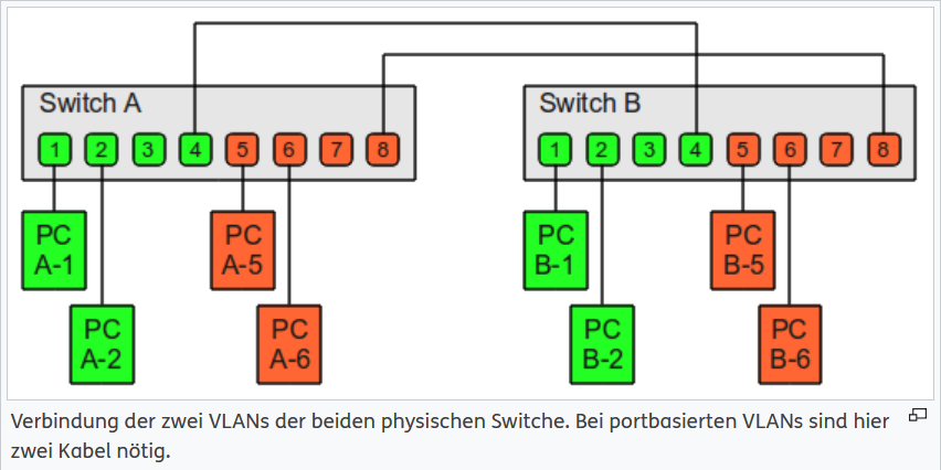
In order to connect the two VLANs here, we need two cables:
From switch A port 4 to switch B port 4 (for VLAN 1) From switch A port 8 to switch B port 8 (for VLAN 2)

Connection of the two VLANs of the two physical switches. Two cables are required here for port-based VLANs.
Note on PVID: For some switches, it is necessary to set the PVID (Port VLAN ID) in addition to the VLAN ID of the port on untagged ports. This specifies which tagged VLAN Ethernet frames should be sent to when they are received on this untagged port. The PVID should therefore match the configured VLAN ID of the untagged port.[1][2]
Tagged VLANs
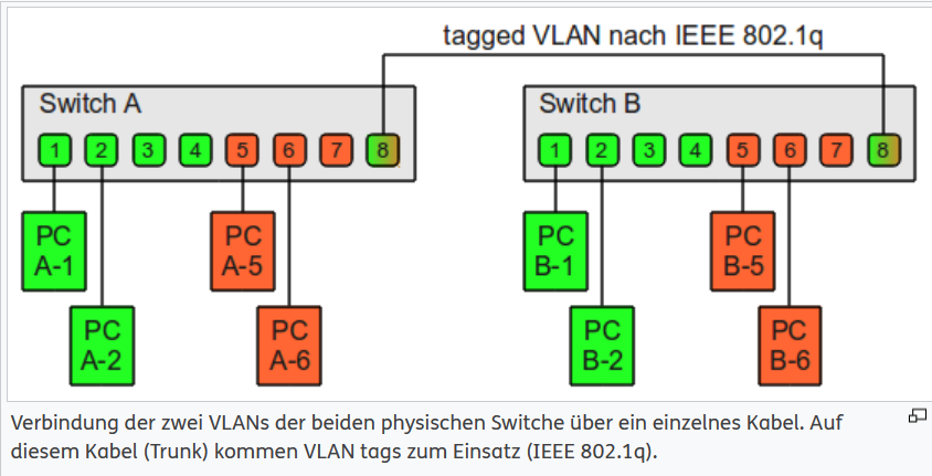
With tagged VLANs, multiple VLANs can be used via a single switch port. The individual Ethernet frames are tagged with tags, in which the VLAN ID of the VLAN to which the frame belongs is noted. If both switches in the example shown can handle tagged VLANs, the mutual connection can be made with a single cable:

Connection of the two VLANs of the two physical switches via a single cable. VLAN tags are used on this cable (trunk) (IEEE 802.1q). Ethernet frame structure
The VLAN tag comes after the MAC addresses in an Ethernet frame:

Source: Thomas Krenn & Security Insider
